In the development and application of foundation models, data preprocessing, model development, training, and inference are the four critical stages. This article focuses on the inference stage. Our previous blog posts mentioned using JuiceFS Community Edition to improve model loading efficiency, with examples from BentoML and Beike.
In this article, we’ll dive into how JuiceFS Enterprise Edition accelerates foundation model inference in multi-cloud architectures. You can learn how it tackles challenges like speeding up data access, efficiently distributing model data in multi-cloud environments, cost-effectively managing large volumes of existing data, and optimizing hardware resource utilization in heterogeneous environments.
Challenges for foundation model inference and storage
The diagram below illustrates a typical architecture for foundation model inference services:
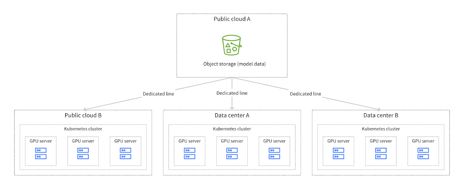
We can observe several characteristics from this diagram:
- The architecture spans multiple cloud services or data centers. Given the current GPU resource shortages in the foundation model domain, most vendors or companies are adopting multi-cloud, multi-data center, or hybrid cloud strategies for their inference services.
- The use of public cloud object storage as the storage point for all model data to ensure data consistency and ease of management. When scheduling inference tasks, specific cloud services may be selected. Data model retrieval requires manual intervention, such as pre-copying data. This is because the scheduling system cannot determine the exact data needed at each data center, and this data is changing. This results in additional costs.
- Large inference clusters with hundreds to thousands of GPUs generate high concurrent data retrieval demands during server initialization.
In summary, the challenges related to foundation model inference and storage focus on:
- Efficient data access
- Rapid cross-region data distribution
- Reading existing data
- Resource optimization
Next, we’ll dive into our practices for addressing these challenges.
Challenge 1: Ensuring high throughput and concurrent data access
Inference tasks often involve handling model files that are hundreds of gigabytes in size, requiring high-concurrency sequential reads. Load speed is a critical concern for users. To meet the performance demands of such scenarios, JuiceFS Enterprise Edition’s distributed cache can create a large-scale caching space. By storing frequently used model data in a cache cluster, data access speed can be significantly improved, especially when launching thousands of inference instances simultaneously. Moreover, for AI applications that frequently switch models, such as Stable Diffusion’s text-to-image service, the cache cluster can greatly reduce model loading times. This directly enhances user experience.
For example, when loading a Safetensors format Stable Diffusion model on a standalone machine with a single GPU, data retrieval from the cache cluster can have a latency as low as 0.5 ms, compared to about 20 ms from object storage. This is nearly a 40-fold performance improvement.
The figure below shows JuiceFS’ distributed cache architecture:
- The inference cluster is at the top.
- The cache cluster is in the middle layer.
- Object storage is at the bottom.
- The metadata service is at the top right corner.
When the inference service is deployed, it first accesses the required model data through the mounted JuiceFS on the inference cluster. If the data is found in the local memory cache of the inference cluster, it’s used. If not, it queries the cache cluster in the middle. If the cache cluster also fails to find the data, it’s retrieved from the object storage.
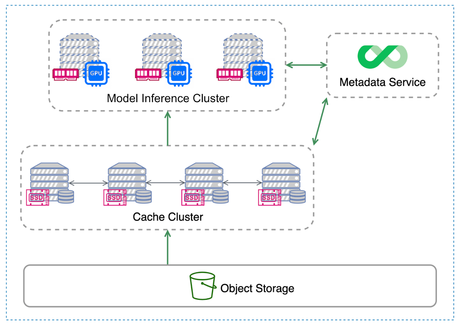
Although the inference cluster and cache layer may appear as separate layers in the diagram, they can be combined in practical applications or deployments if GPU servers have NVMe SSDs.
In the example where each GPU server is equipped with multiple SSDs, with three SSDs per GPU server, one SSD is used for local caching and the other two SSDs serve as storage disks for distributed caching. In this case, we recommend the following deployment approach: deploying two clients on a GPU server—one for the FUSE daemon and one for the cache cluster client.
When an inference task needs to read data, it first attempts to read from the local FUSE mount point. If the local cache does not contain the required model data, the inference task accesses the distributed cache through another JuiceFS client on the same server. Once the data is read, it’s returned to the inference task and cached on the two SSDs managed by the cache cluster as well as the local FUSE mount point for faster future access.
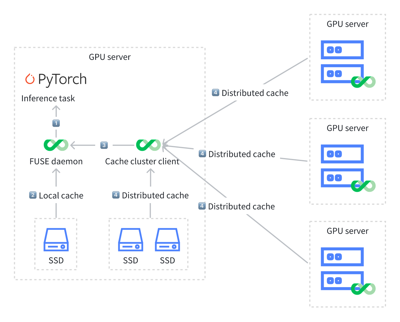
Deploying two clients on a GPU server has two benefits:
- Reduced network overhead: Local caching minimizes network communication costs. Although GPU servers communicate over high-speed network cards, network communication still incurs significant overhead.
- Distributed cache cluster effect: The cache cluster client allows inference tasks to access data on other GPU servers. This achieves the effect of a distributed cache cluster.
Challenge 2: Quickly distributing model data to compute nodes in multi-cloud and hybrid cloud architectures
In multi-cloud and hybrid cloud architectures, data is spread across different cloud platforms and data centers. Traditional manual intervention, copying, and migration methods are not only costly but also complex to manage and maintain, including various issues such as permission control.
JuiceFS Enterprise Edition's mirror file system feature allows users to replicate data from one region to multiple regions, creating a one-to-many replication relationship. The entire replication process is transparent to users and applications. Data is written to a specified region, and the system automatically plans and replicates it to other regions.
The diagram below shows the data writing and reading process in a mirror file system. It shows two regions: the source region and the mirror region. When data is written to the source region, JuiceFS automatically replicates the data from the source region to the mirror region.
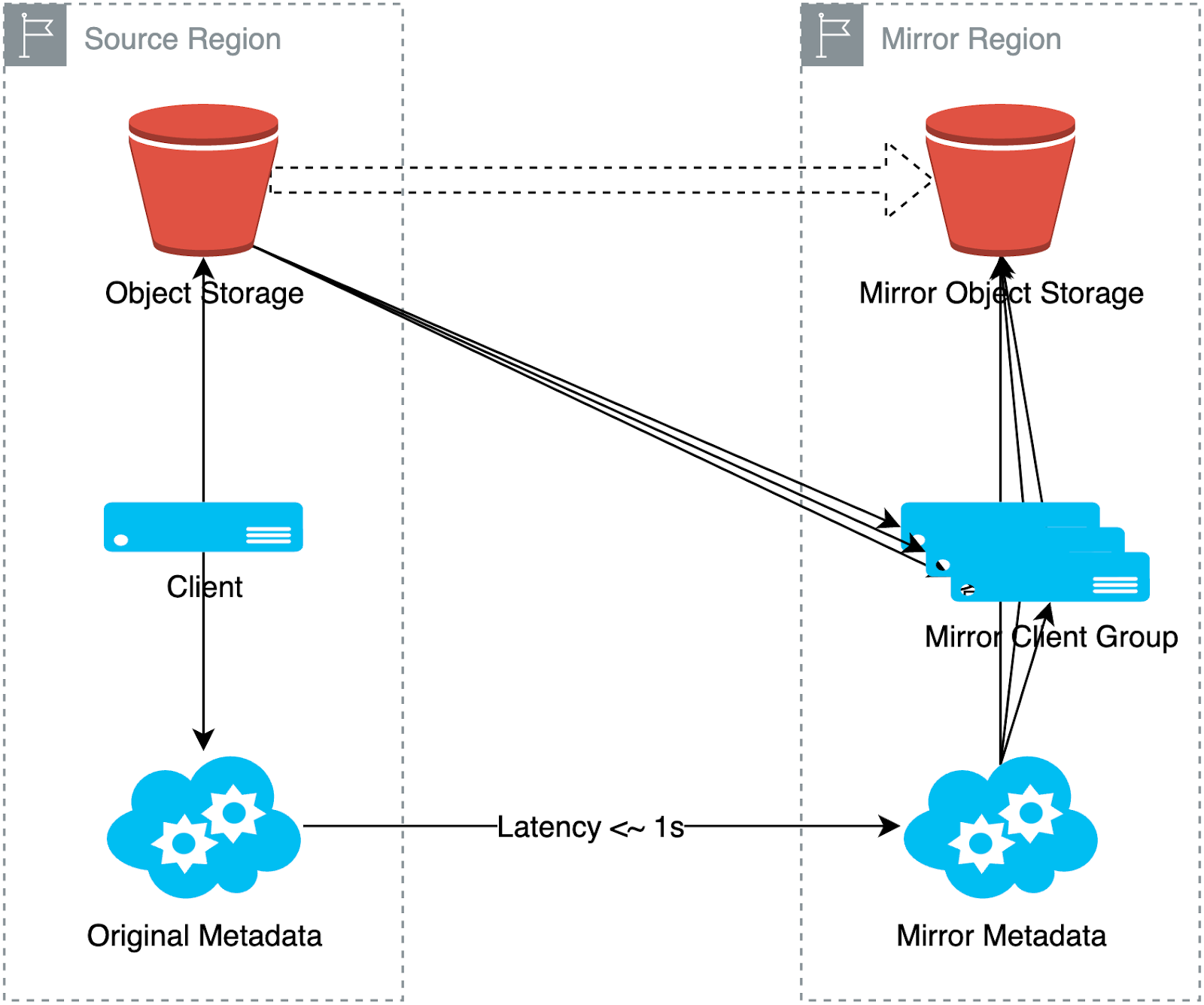
When reading data, the client in the mirror region first attempts to pull data from the object storage in its own region. If the data is missing or has not yet arrived due to synchronization delays, it automatically falls back to the source region storage and pulls data via a secondary data source link. Thus, all clients in the mirror region can ultimately access the data, although some data may come from the backup data source.
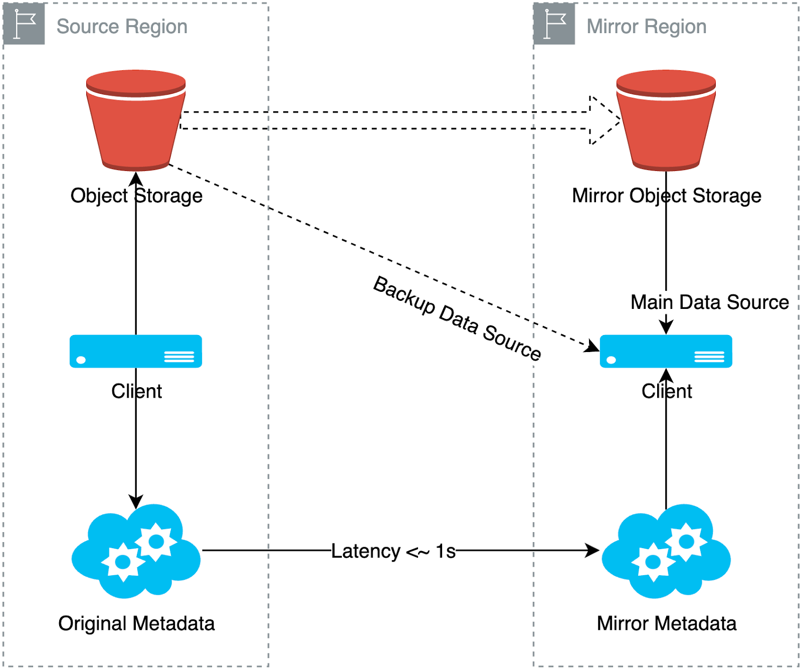
An example of data write process
This example shows a foundation model enterprise's deployment of a mirror file system, similar to the typical architecture diagram shown at the beginning of the article. At the top of the diagram is a central cluster, which serves as the source of data production.
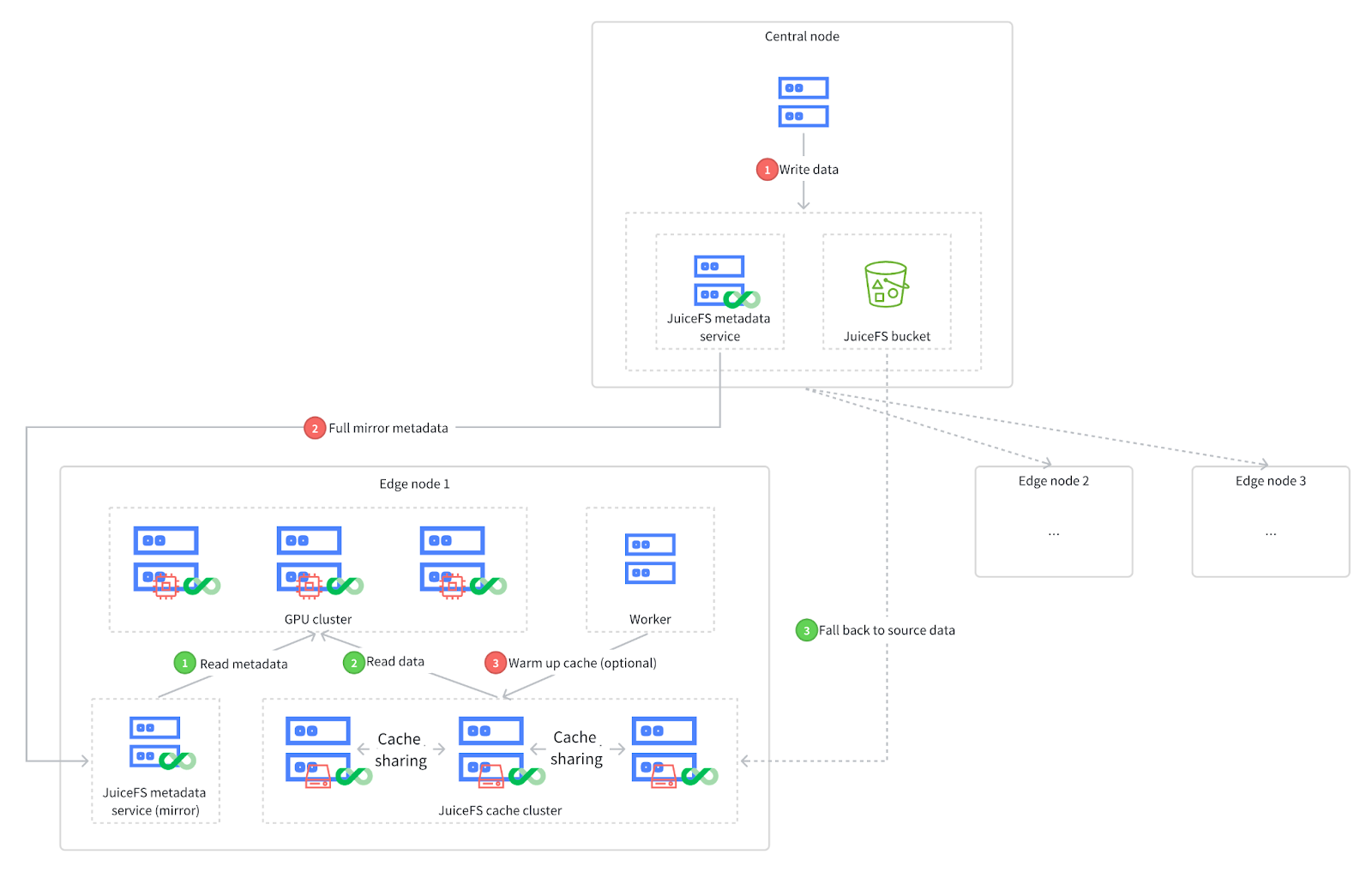
The data write process is as follows:
- Writing data: Data is initially created and written in the central cluster.
- Full mirror metadata: After data production is complete, it’s written to JuiceFS, triggering a full metadata mirror process. As shown, data is mirrored from the central JuiceFS metadata service to one or more edge clusters (three in this case), allowing edge clusters to access metadata locally.
- Cache warming up (optional): This step optimizes data access speed. When new data is added, in addition to replicating the metadata, it’s also desirable to access this data locally. In environments without object storage, distributed cache functionality can be employed by deploying a distributed cache cluster in each data center. By warming up the cache, the new data is copied to the cache clusters in each edge cluster, thereby accelerating data access.
An example of data read process
The data read process is as follows:
- Accessing the mirrored metadata service: As shown in the green numbers in the diagram, when the GPU cluster needs to retrieve model data, it first accesses the mirrored metadata service.
- Reading metadata and retrieving data: After retrieving metadata, the client first attempts to obtain the required data from the cache cluster in the data center. If cache warming up has been done, the required model data can usually be found in the data center’s cache cluster.
- Falling back to source data: If data is not found in the cache cluster for any reason, there is no need to worry. This is because all cache cluster nodes will automatically fall back to the central object storage bucket to retrieve the original data.
Thus, the entire data reading process is smooth. Even if some data has not been warmed up or new data is not yet successfully warmed up, it can still be fetched from the central JuiceFS bucket through automatic fallback.
Challenge 3: Cost-effective and efficient access to large volumes of existing data
In addition to the challenges of data distribution in multi-cloud and hybrid cloud architectures, a common need is to migrate large amounts of accumulated raw data (for example, several petabytes) directly into JuiceFS. This need increases the complexity of large-scale data management and may require adjustments like data dual-writing. This may impact normal application operations.
The importing object storage metadata feature in JuiceFS Enterprise Edition allows for more efficient data import with minimal impact on operations. Users only need to continuously import metadata without copying data. The imported data can be accelerated through JuiceFS' distributed cache, improving data access speed. The following diagram shows the workflow of this feature:
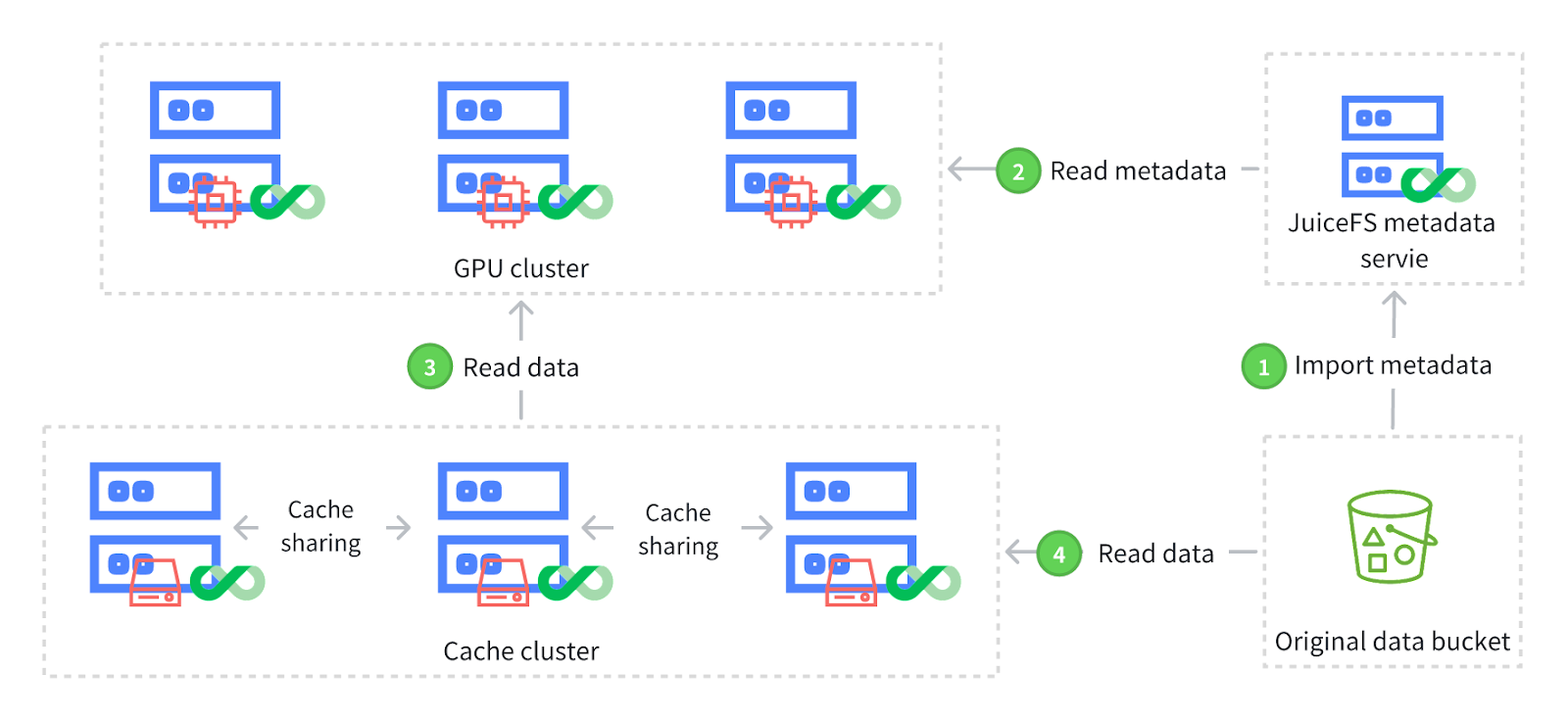
The workflow of importing object storage metadata:
- Import metadata: Using JuiceFS command-line tools, users can selectively import metadata from specific parts of the original data bucket without importing the entire bucket. This process uses prefix matching, involves only metadata import, and completes quickly as it does not copy data in the object storage. Metadata import is not a one-time operation. As the original data grows or changes, users can perform incremental imports without worrying about additional costs from duplicate imports. During each incremental import, the system only imports metadata for new or modified data, avoiding the re-import of already processed files. This prevents extra overhead.
-
Read metadata: After importing metadata into JuiceFS, applications (for example, inference tasks) can access the imported data through the JuiceFS client. Applications can start immediately without waiting for data to be copied from the original bucket to JuiceFS.
-
Read data: In scenarios like inference, distributed caching is often configured to optimize data access. Since only metadata was imported in the first step and not the actual data, the initial read from the distributed cache will not retrieve the data directly.
-
Fall back to original bucket and cache data: This step involves retrieving data from the original bucket through the distributed cache system. Once data is read, it’s automatically cached in JuiceFS' distributed cache. This avoids the need to access the original bucket for subsequent data reading, thus enhancing data access efficiency.
Following these steps, inference tasks can quickly access existing data and benefit from the performance boost of distributed caching.
Challenge 4: Optimizing hardware resource utilization in heterogeneous environments to enhance storage and compute performance
In heterogeneous environments, a system integrates various types or configurations of hardware devices. To maximize the value for enterprises, it’s crucial to fully utilize these heterogeneous hardware resources. In the following example, we have three servers, each equipped with different numbers and capacities of SSDs. Based on the total storage capacity of each server, the cache capacity ratios for these servers are set to 1:2:3.
| No. | Number of SSDs | SSD capacity (TB) | Total capacity (TB) |
|---|---|---|---|
| Server 1 | 2 | 4 | 8 |
| Server 2 | 2 | 8 | 16 |
| Server 3 | 3 | 8 | 24 |
By default, JuiceFS' distributed cache assumes that all servers have the same hardware configurations. Therefore, all cache nodes have equal weight. Under this configuration, the system's overall performance is limited by the server with the smallest capacity—in this case, 8 TB—leading to underutilization of other servers’ storage. Up to two-thirds of server 1’s cache potentially is not used.
To address this issue, we introduce the cache node weight concept, allowing users to dynamically or statically adjust the weight of each GPU node based on actual hardware configurations. For example, you can set the cache weight of server 1 to a default value of 100, server 2 to 200, and server 3 to 300. This corresponds to the 1:2:3 SSD capacity ratio. By setting different weights, you can more effectively use the storage resources of each cache server, optimizing overall system performance. This approach provides a typical solution for handling servers with different hardware configurations.
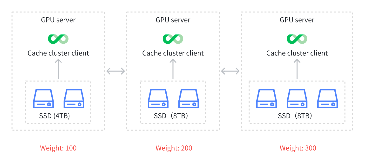
Beyond this scenario, cache node weight can be applied in other situations as well. For example, GPU servers tend to encounter failures, and users may need to take one or two servers offline weekly for hardware maintenance. Since a server shutdown results in the loss of cached data or temporary inaccessibility, this could affect the cache cluster's hit rate. In this case, the cache node weighting feature can also be used to minimize the impact of server failures or maintenance on the cache cluster’s utilization.
Future plans
Finally, let’s explore the improvements we plan to make in inference scenarios and other potential applications.
-
We plan to introduce a multi-replica feature in the distributed cache. Currently, data in the distributed cache system typically exists in a single replica format. This means that if a server (such as a GPU server) unexpectedly fails, the cached data on that server is lost due to the lack of a backup, directly impacting cache hit rates. Since such failures are sudden, we cannot gradually migrate data to other nodes through manual intervention.
In this context, single-replica caching inevitably affects the efficiency of the entire cache cluster. Therefore, we consider upgrading from single-replica to multi-replica caching. The benefits of this upgrade are clear: although it consumes more storage space, it can significantly improve cache hit rates and availability in scenarios where servers frequently fail.
-
We’re exploring the implementation of a user-space client. Currently, the file system based on FUSE mounting effectively implements file system functions. However, since it relies on the Linux system kernel and involves multiple switches and data copies between user space and kernel space, there is some performance overhead. This limitation is particularly obvious in serverless and Kubernetes environments on the cloud. FUSE mounting may not be permitted. This restricts the application scenarios of JuiceFS.
Therefore, we consider developing a pure user-space client. This would be a component that does not rely on kernel space. It can significantly lower the usage threshold and provide services in environments where FUSE is unsupported. Moreover, by avoiding frequent switches and memory copying between kernel space and user space, this client could potentially deliver significant performance improvements, especially in GPU-intensive environments requiring high throughput.
However, a potential drawback of this client is that it may not be as transparent as a POSIX interface. It requires users to implement functionalities by incorporating specific libraries (for example, the JuiceFS library). This approach might introduce intrusion into the application.
-
We aim to enhance observability. The JuiceFS architecture includes multiple complex components, such as GPU servers, the cache cluster, object storage through dedicated lines, and cache warm-up. Given this, we plan to introduce more convenient tools and methods to improve the overall observability of the architecture. This will help JuiceFS users quickly and easily locate and analyze issues. In the future, we’ll further optimize the observability of various components, including distributed caching, to assist users in fast problem diagnosis and resolution when issues arise.
If you have any questions or would like to share your thoughts, feel free to join JuiceFS discussions on GitHub and community on Slack.


